 FEATURED
Application Development & Modernization
Uplift enterprise IT with cloud-native modernization services that transform critical applications and empower peak performance.
Cut through the complexity of cloud technology and unlock its full potential with multi and hybrid cloud solutions and services.
Unlock collaboration that uplifts your organizations with cloud-based tools from Microsoft and Cisco to bring teams together.
Conquer security compliance complexities with targeted advising and assessment tailored to your company’s unique circumstances.
Form the foundation of more secure, more successful operations with IT data center solutions and strategies.
Leverage DevOps and cloud-native principles to achieve business goals, enhance software delivery, and future-proof infrastructure.
Design a reliable networking solution around the requirements of your organization.
Implement secure, scalable, and repeatable security measures shaped to serve your specific business needs.
Stay ahead of network needs and the competition with tailored optical transport and network infrastructure solutions.
FEATURED FEATURED
 FEATURED
 FEATURED
 FEATURED
 FEATURED
 FEATURED
 FEATURED
 FEATURED
 FEATURED
 FEATURED
 FEATURED
PETER WELCHER | Solutions Architect
I recently wrote two blogs about why an organization might want Cisco SD-Access (“SDA”) and Cisco Catalyst Center: pros, cons, where SDA might be appropriate, where not appropriate, and some other advice.
Links to them:
This blog introduces key concepts and terminology regarding Cisco SD-Access. It will cover device roles and high-level choices that include how to integrate WLAN, the inter-site transit mechanisms, and a little about how to use Cisco Catalyst Center (formerly DNA Center.
Establishing the terminology will set us up to take a more in-depth look at components of SD-Access in subsequent blogs. Some of this material duplicates parts of the prior two blogs. The rationale here is to have the terminology and high-level design in one document with that specific focus.
Device Roles, Terminology
SD-Access (“SDA”) introduces some new terminology around the switches’ roles in the network. This is a necessary pre-requisite before we can discuss SD-Access itself.
One critical concept in SD-Access is a “fabric site.” A fabric site is a single geographic location or building(s) with an SD-Access VXLAN fabric extending across it. Contrast this to a “fabric domain,” which is a collection of such sites.
Usually, a fabric site will consist of one or more distribution switches and a number of dual-homed access switches – using the prior terminology. We refer to this as a “spine/leaf” topology when it’s in a data center.
So far, these blogs have not yet commented on what’s different about SD-Access from a usage perspective.
A fabric site uses VXLAN tunnels that route over the underlay infrastructure. These allow robust transport of Layer 2 traffic. The result is like having VLANs that exist on every switch in the fabric site, without the stability risks that Layer 2 entails.
Switches in SDA have roles, reflecting what they do within SDA. We still may discuss the position of a device in a hierarchical topology as core, distribution, and access. One should generally design a uniform topology along those lines – standardization is the key to simplicity and scalability.
The access switches usually act as “edge nodes (EN’s)” – computers and other devices attach to edge nodes. Edge nodes learn about the attached devices and register them with the control nodes, which track every end device within the fabric site.
In a two-tier topology, the distribution switches generally link to the rest of the network, and so they will probably act as SDA “border nodes (BN’s).”
Border nodes are the entrance and exit from the VXLAN fabric. Border nodes are the site exit and gateway to the rest of the network and the Internet.
Border nodes will connect to either a transit fabric for communication to other SDA sites or to a fusion router or firewall for communication outside the organization or between virtual networks.
You can dedicate some border nodes for the Internet and have the others connecting to the rest of the organization’s network. Or both uses can be combined into one or two border nodes.
Border nodes may also have the edge node role if you plan on connecting devices to them. Typically, they would be in central closet(s) which might or might not contain connections to end user/system devices.
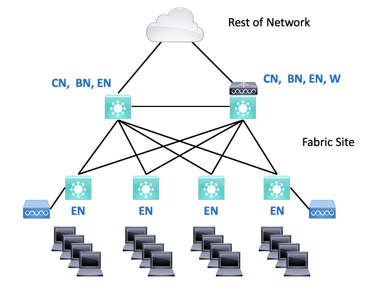
Note the switches marked “EN” in the diagram below. It shows a site where every switch is an edge node.
The core switches might be the border nodes in a three-tier topology (core/distribution/access). The distribution switches could be underlay-only “intermediate nodes,” providing routed connectivity for the access switches. They can also act as edge nodes when end systems are plugged into them.
You could also build a network with three layers, core-distribution-access, and even have two or more dedicated border nodes “above” the core switches, with the core switches as intermediate nodes. That is generally only done at very large sites for cost reasons, or where clear separation of functionality is desired.
One might also design to have SDA border nodes only, located at one or two datacenters, for connecting the user domain to the datacenter(s).
An SDA site needs one or more control plane nodes (“control nodes” for brevity). They can be combined border and control nodes or separate devices when necessary for scaling reasons. (Read The Fine Manual, RTFM, for Cisco’s recommended scaling numbers.)
Control plane nodes are LISP Map server/Map resolver nodes, and act similar to a phone book, resolving IPv4, IPv6, and MAC addresses to their location in the network, a specific edge node.
SDA diagrams typically indicate roles by placing letters alongside switch icons, so you might see BN|CN|EN for a combined border, control, and edge node. Or even “BCN.” And “W” gets added for a wireless controller – we’ll come back to that below. This is shown in the diagram above.
Fabric in a Box, or FIAB, refers to a single switch performing the BN, CN, and EN roles. FIAB is used for a small site with a single switch present.
You can connect older or less functional switches to the edge nodes. This is one way to support legacy IoT, outdoor, and other such uses. These extended node switches support VLANs and trunks and SGT assignment. The EN provides inter-VLAN traffic enforcement.
Recently policy extended nodes were added: they are switches that can do SGT enforcement, which allows full micro-segmentation. They are especially needed for industrial REP ring topologies.
Note: Cisco’s abbreviations have been shifting, with edge nodes becoming “fabric edge” or “FE” to free up “EN” for extended nodes (in an IOT / OT context). You can probably guess what a “PEN” is.
Generally, an organization has DNS, NTP, ISE, DNAC, and other services in a shared services block in one or more data centers.
Wireless Integration Choices
In SDA, wireless APs get connected to ENs. However, there are choices as to how they are integrated into SDA.
They can be managed via a WLC in a services block, as was done in the past. This can be helpful in migrating from a legacy wireless design to SDA-based wireless.
In this approach, the AP’s reach the WLC via the underlay and global routing table. This is referred to as Over The Top (OTT) design in SDA, and called “local mode.” For migration, you might first deploy and migrate the LAN side of things and either leave WLAN as is or migrate it later. With OTT, wireless policy enforcement is done at or near the WLC, either per-SSID or (recently) via SGT assignment at the controller. One drawback is that CAPWAP tunneling consolidates traffic at the WLC, which can become a bottleneck when aggregating traffic from a large number of the new higher-speed APs.
If you want local switching, FlexConnect over SDA fabric is not currently supported, but it may work. (It was expected soon in an upcoming release at the time of this writing a while ago.) Another choice is to do fabric wireless. The attraction of fabric wireless is that the APs act more or less like the edge switches. APs, acting like the switches, then tunnel traffic into the fabric and assign SGT’s. This means that your wired and wireless users’ traffic follows the same paths through the network and is handled the same as far as segmentation enforcement. They use the same addressing. As a bonus, doing this distributes the AP traffic load among wired switches, with no CAPWAP. Since SDA uses VXLAN tunnels too, in effect extending VLANs across the fabric site, wireless roaming within the site just happens, in effect, with no CAPWAP tunneling. High-speed all the way! Oh, and wired and wireless guest traffic are both handled the same way.
SDA fabric wireless does currently require a WLC at each site (“fabric wireless controller”). This could be a physical WLC. However, depending on scaling requirements, a virtual WLC can now run in an AP at the site, or in one of the switches (combined role or dedicated). The virtual WLC in a switch (“embedded Catalyst 9800 WLC”) is rated as supporting 200 APs and is, more or less, a role checkbox in the DNAC GUI. Using an embedded WLC is included in the switch license required for SDA (or was, at the time this was written – Cisco licensing being subject to frequent changes).
Note that a WLC per site does not provide site survivability if the site gets cut off: DNS and ISE are needed.
You can mix OTT and fabric WLC, but there is no wireless roaming between AP’s using the two different approaches. Due to this, in a migration, the best practice is to migrate a floor at a time or a building at a time.
Transit Mechanisms
There are three ways of interconnecting fabric sites within an SDA fabric domain:
We will refer to the network connecting the sites as the “backbone network.”
IP Transit has the site Border Nodes route into the routed backbone network. SDA typically configures BGP and a VRF for each SDA VN (virtual network) on the border nodes. You can then configure matching BGP and VRF’s in the connected backbone network device and across your backbone. (Some call this a “VRF rainbow” because of how it is typically diagrammed.)
Alternatively, you can connect the various fabric VRFs to the global routing, making the backbone router a fusion router. While this discards segmentation in the backbone, SXP or other means can allow the use of the segmentation for enforcement at datacenter firewalls.
DNAC will configure the BNs for you (assuming you want BGP), but the rest is up to you.
If you do not already have VRFs across your backbone network, a substantial amount of configuration would be required to set that up.
Thus, IP Transit is just IP routing between the sites and the rest of the network, with or without preserving VRFs.
SD-Access Transit (or “SDA Transit” for short) uses LISP to trigger VXLAN tunneling from site BN’s to another site or datacenter BN’s. If you check a box in DNAC, datacenter or other central BN’s become Internet exit points, feeding traffic into fusion firewalls.
SDA Transit provides a VXLAN tunnel overlay interconnecting your fabric sites and preserving the VRF / VN segmentation, all auto-configured via DNAC.
SDA Transit cleanly separates overlay (SDA fabric user/device addresses) from the underlay. The underlay must be able to route to the loopback addresses on the switches. Routing between underlay and overlay only takes place on fusion firewalls or routers.
By contrast, IP Transit has to handle all the user addresses and routing as well in the backbone network. That means redistribution at every site border node to backbone network handoff, somewhat more complex, and distributed routing logic. That’s do-able if IP Transit is a better fit for your organization.
SDA Transit requires a large campus or regional setting with adequately low latency. For networks with more latency / greater geographic spread, one of the other transit techniques will be needed. Or use different fabric domains, each of which internally does SDA Transit.
SD-WAN Transit is the upcoming GUI integration of DNAC and Cisco SD-WAN, details TBD. It could use the same options as IP Transit. “VRF rainbow” from the SD-WAN router to the adjacent SDA fabric BN’s seems likely to be a workable interim solution.
Note that SD-WAN Transit might be useful where an organization has a regional fiber or other high-speed network interconnecting campuses or buildings but needs to also connect small sites with slower / higher-latency connection or field offices across the WAN, etc.
How Can Cisco Catalyst Center Be Used?
For those new to SD-Access, one puzzling factor is where Cisco Catalyst Center (“CCC”, previously DNA Center) fits in. The source of confusion is that DNA Center can be used in several ways.
CCC is a key GUI component in SD-Access, providing automation and management of large numbers of switches. It may run on a single server, or a cluster for High Availability, or as a service in the Cloud.
There are several ways to use CCC:
Even if you have a brownfield existing network, you may want to do LAN Automation for consistency with later new deployments that do use LAN Automation.
Links
Conclusion
You should now be ready to start learning more deeply about various aspects of SDA. It was critical to establish the terminology before plowing into finer detail about key topics.